
tl;dr
- Due to a hardware bug the Sparkfun LiPower shield will discharge a LiPoly battery beyond a level from which it can be recharged, effectively killing the battery.
- There is no complete software workaround to stop this from happening
- The shield should never be connected to a battery when the Arduino is connected via the USB port. Doing so will most likely permanently damage the computer, the Arduino or the LiPower shieldDue to the above, the example code which is supplied on the Sparkfun product page is only useful if you are using a dedicated USB to serial adapter and never one which supplies any voltage to the Arduino. Only the TX, RX and GND lines should be connected, the Arduino should be powered via the LiPower shield battery
Introduction
The Sparkfun LiPower Shield provides an easy and convenient way to power your Arduino projects from a small, high capacity LiPoly battery. It provides:- A MCP73831T to charge the LiPoly battery from either the LiPower Shield's mini USB or optional power header
- A TPS61200 to boost the nominal 3.7V output of a LiPoly cell to a 5V voltage that the Arduino can power itself from
- A MAX17043G to allow the Arduino to monitor the battery's voltage and automatically calculated charge percentage via the I2C interface
All of this is contained in a shield that can be plugged into the top of your Arduino and allow you to sever that power cord. Unfortunately the shield has a hardware bug which will cause the Arduino to fully discharge the LiPoly battery beyond a voltage from which the battery can be recharged. This effectively kills the battery and the only option is to buy a new one, something that I tested out first hand ;) The product page on Sparkfun mentions the hardware bug but doesn't document it. This blog post should hopefully do so, to ensure that other users don't have to go through the hassle and expense of buying a new battery
A Crash Course in LiPoly Batteries
Lady Ada has a fantastic introduction to Li-Ion and LiPoly batteries at:http://learn.adafruit.com/li-ion-and-lipoly-batteries
For the purposes of this post the most important part is discussed here:
http://learn.adafruit.com/li-ion-and-lipoly-batteries/voltages
A 3.7V lithium battery, as used for the LiPower shield, should be used until it reaches a minimum voltage of 3.4V, at this point its internal remaining capacity is effectively zero. The battery will still continue to produce a voltage between its contacts all the way until its built in protection circuit kicks in. The protection circuit is built into a typical Lithium cell and ensures that if a cell voltage drops below a limit (typically 2.7 to 3.0 V http://www.hardingenergy.com/pdfs/5%20Lithium%20Ion.pdf ) the battery is never allowed to recharge. Below this voltage the battery chemistry causes copper shunts to be formed, effectively turning the battery into a resistor. Attempting to recharge the battery that has reached this limit will rapidly start dissipating all that heat into the cell, leading to thermal runaway, and causing the cell to set on fire:
The protection circuit therefore makes sure that if the cell voltage drops dangerously lower than the safe recharge voltage the cell is disconnected. The cell is now considered dead and should be disposed of.
Any device which therefore uses LiPoly batteries should ensure that if its LiPo voltage is approaching the minimum 3.4V they should either stop using the LiPoly battery completely or to minimise it as much as possible. The battery should then be recharged. Continuing to draw current from it, and dropping its voltage lower will risk the protection circuit cutting in and permanently disabling the battery
A closer look at the LiPower Shield
This is the schematic for the LiPower Shield: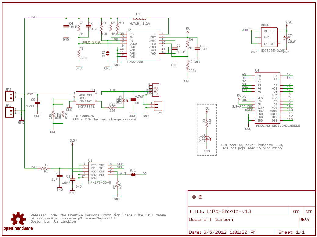 |
| Taken from the PDF on the SparkFun product page |
Lets run through the components and some of the design decisions in this schematic
A MIC5205-3.3V LDO is used to directly take the battery voltage down to 3.3V. This is used exclusively to power the MAX17043G fuel gauge. At absolute maximum the MAX17043G uses 75μA, and wen not required to talk I2C to a micro-controller it enters a sleep mode which uses at maximum 3μA. At the lowest current on the MIC5205 datasheet of 100μA, the MIC5205 has a worst case dropout of 70mV. Meaning that to keep the fuelg gauge IC active by providing a 3.3V requires at minimum 3.37V on the input. Note that the MIC5205 also has an enable line, this is permanently tied to the battery input voltage, and has a trigger level of 2.0V, meaning that it is effectively always on when a battery is connected.
Next we have the MAX17043G fuelgauge IC. This clever little chip makes an estimate on how much charge the battery has remaining based purely on its voltage. Typically a coulomb counter is used to monitor batteries, they literally count the coulombs that pass between a battery and a charger or load, and therefore have very high accuracy if properly used. Their disadvantages are well discussed in the MAX17043G datasheet. The MAX17043 on the other hand monitors the battery based purely on the voltage, the clever algorithms mean that this estimate is typically no more than a couple of percent out from the real value.
The chip's I2C interface allows it to be interrogated for current charge percentage as well as raw voltage reading. It also has a software programmable alarm output, which is connected to the Arduino D2 pin. This typically allows us to set a lower limit of say 10%, and to be notified when we have reached this without constantly interrogating the chip via I2C. This is useful as it should then allow the device to take action to power itself down and refuse to switch on until the battery is recharged
The MCP73831T handles the battery charging. It is self powered via the charging input and does not place any load on the battery. It has a programmable maximum charging current with a maximum of 500mA. By default this is limited to 100mA on the LiPower shield, which allows a 100mAh battery to recharge in one hour, but will take about 20 hours to charge a 2000mAh cell, ouch! I recommend using the provided space for R10 to increase this current to 1/2 to 1/4 of your cells maximum capacity, so that it can be recharged in 2-4 hours. Note that this chip also provides a charging LED. This LED should more accurately be called "The MCP73831T Has Power LED". It does not provide any feedback that the battery attached is actually charging, it simply means that there is voltage at the output of the MCP73831T. Connecting a battery which has had its protection circuit kick in, the battery is un-rechargeable, will cause the LED to light up, making you think that it may actually be managing to charge the battery. It isn't.
Finally we come to the TPS61200 boost converter This takes the battery voltage and boosts it up to the 5V that the Arduino, and any other devices that you may have, can make use of. It's able to drive up to 1000mA on its output, although its efficiency is drastically cut at this point and its likely to to enter thermal shutdown without adequate dissipation Realistically it's able to drive up to about 600mA at over 90% efficiency. As a feature it's also able to disable itself, this is called the Under Voltage Lockout, or UVLO. This ensures that if a battery falls below the the programmed voltage the boost converter disables itself and continues to draw at most 2μA.
The Hardware Bug
If you've had a look at the TPS61200 as shown on the LiPower shield schematic you've probably spotted the bug. On the UVLO pin there's an annotation which reads:UVLO=2.52V
Oops. This means that the protection that the TPS61200 provides will only kick in at 2.52V, much below the safe operating range of the battery, and far below the voltage that the built in protection circuit on the battery will kick in at. The TPS61200 will therefore keep functioning, and will keep attempting to provide a 5V output to the Arduino, all the way until the battery is permanently unusable.
The Workaround
The Sparkfun page makes mention that there's a bug, and that a workaround should be possible:There is a known hardware bug that will allow the LiPo to discharge below the point where the charging circuit will revive it. Thanks to the on-board fuel gauge, however, some clever programming could keep your project from draining the battery as it gets too low.So, let us presume that we are monitoring the battery using the fuel gauge, and we notice that the battery voltage has fallen dangerously low. If our circuit is able to do so we should stop trying to use the 5V output from LiPower board. This means disabling anything such outputs, and putting any shields available into sleep states, before finally halting the Arduino, causing it to use as little power as possible.
In reality such a solution is not always possible. Even presuming that your circuit is able to switch most of itself off you are still looking at a possible disharge current somewhere in the mA range, the linear regulators on the Arduino to produce clean 5V and 3.3V won't help matters. This will still quite quickly discharge a battery beyond its cutout point.
I would therefore claim that while a workaround may be possible in some circumstances, it will at best help the issue rather than resolving it.
The Fix
The correct fix is to replace the UVLO programmable resistors so that the UVLO cutout is set to 3.4V. Although this is far from easy, unlike the programmable current on the MCP73831T there are no spare through hole pads to easily change the values of these. The only option is to remove them and replace them. Given that they are tiny SMT parts this is far from easy but is possible.In the above fix the booster, the 3.3V LDO and the MAX17043G fuel gauge continue to use power from the battery. Given that everything is now in a deep sleep state the drain should be in the order of tens of μAs, which would require weeks before even a heavily discharged 100mAh LiPoly cell finally dies. By this point you should have hopefully noticed and done something about it.
One other alternative would revolve around some kind of soft-power circuit built on MOSFETs between the battery and the LiPower. This does not require modification of the shield. Using the Alert output of the MAX17043G will allow it to disconnect the battery and to fully power itself off automatically Alternative the Arduino could be used to issue the same battery disconnect.
A Note on the Example Code
The example code from the Sparkfun page is used to illustrate talking to the fuel gauge via I2C, with the output being printed on the Arduino serial terminal. The LiPower shield should never be connected to a battery, and directly to the Ardunio when the Arduino is using either it's USB port for power or the Aux connector. Doing so will result in there being two voltage sources, both the Lipoly cell and the Arduino source. So, to test the shield out, and to talk to the fuel gauge it would be reasonable to try running the code with the Arduino powered via USB and the battery disconnected. This will not produce any readings from the fuel gauge in the serial terminal. Adding extra debug to the program will let us see that we are apparently sending the init commands to the fuel gauge without issues, but that we aren't getting any data back. So, what's going on?As discussed above the fuel gauge is powered from the battery, so with no battery connected we can't actually talk to it as it isn't powered. The mystery of why we can't seem to read data from it while writing data to it is explained by the I2C bus being extremely simple. When we're writing data we simply bang the bits out on the pins. We have no confirmation that anything has happened, but we presume that it was successful On the read side we expect that the other side of the I2C bus will respond, when it never does we don't time out, we simply wait forever until some data arrives. Hence it looks like the program is hung.
To check that the LiPower shield is therefore working there are two solution. The first is to not use serial terminal at all and to get the Arduino to read the data and provide it on some kind of display. In the photo at the top of this post I've used an SPI LCD to provide that feedback, although it's possible to simply use some seven segment displays.
The other solution is to continue using the serial line debugging. This can be done by powering the Arduino from the LiPower shield, and instead of using the build in USB->Serial adapter on the Arduino board, to instead hook up a dedicated USB->Serial adapter and only connect the GND, TX and RX pins. It should also be possible to modify the tracks on the Arduino board so that the built in USB->Serial adapter is usable for serial communications, but does not provide power to the Arduino.
I would also say that running the fuel gauge init command is completely unnecessary The fuel gauge is intelligent enough to perform this re-init itself when a battery is disconnected and re-connected. And keeping its calculations active will ensure that it may achieve a higher degree of accuracy in gauging how full the battery is.
Final Notes
Understanding the operation of your components and their limitations in an electronic circuit is an import part of engineering a project. While a lot of Arduino development can be done successfully by stacking shields together and making basic modification it's occasionally possible to run into situations where simple things that should work simply don't. This is one of those occasions Understanding and disentangling why typically revolves around taking all the parts and learning about their limitations and how you have implemented them.I believe that the LiPower shield is still a great product, it provides a lot of functionality for a minimum amount of effort, with the caveat that it's important to understand its limitations. The bug is indeed slightly annoying, but it can be mitigated, and the implementation of a "proper" solution revolving around a soft battery disconnect is probably what any circuit using a LiPoly battery should implement.